SNMPv3: The SNMPv3 Agent supports the following set of security levels as defined in the USM MIB (RFC 2574) :
noAuthnoPriv - Communication without authentication and privacy.
authNoPriv - Communication with authentication and without privacy. The protocols used for Authentication are MD5 and SHA (Secure Hash Algorithm).
authPriv - Communication with authentication and privacy. The protocols used for Authentication are MD5 and SHA ; and for Privacy, DES (Data Encryption Standard) may be used.
The main difference between SNMPv3 and v2 (or v1) is that the v3 version addresses the security and privacy issues. For example, in SNMPv2, passwords are transmitted in plain text, whereas v3 uses encryption.
The advantages are given below, in brief:
1. Authentication
2. Privacy
3. Authorization and Access Control
4. Remote configuration and administration capabilities
Security Models and Security Levels Supported by Cisco IOS
| Security Model | Security Level | Authentication | Encryption Type |
|---|---|---|---|
| SNMPv1 | noAuthNoPriv | Community string | None |
| SNMPv2c | noAuthNoPriv | Community string | None |
| SNMPv3 | noAuthNoPriv | User name | None |
| AuthNoPriv | MD5 or SHA | None | |
| authPriv | MD5 or SHA | CBC-DES (DES-56) |
Access-List: There are two types of access lists, Standard Access Lists and Extended Access Lists.
Extended Access Lists can use the following information for packet filtering:
1. Source address
2. Destination address
3. Source port
4. Destination port
5. TCP synchronization information.
Wild card masking : Wild card masking is used to permit or deny a group of addresses. For example, if we have a source address 185.54.13.2 and want all the hosts on the last octet to be considered, we use a wild card mask, 185.54.13.255.
Special cases : Host 185.54.13.2 is same as 185.54.13.2 with a wild card mask of 0.0.0.0, considers only specified IP.
Any is equivalent to saying 0.0.0.0 with a wild card mask of 255.255.255.255. This means none of the bits really matter. All IP addresses need to be considered for meeting the criteria.
The following options are true about access lists:
1. Controlling traffic through a router, and
2. Controlling VTY access to a router's VTY ports
Broadcast traffic may be controlled by using storm control or other means. An ACL can not identify any virus or malware. You need special anti-malware software, such as Advanced Malware Protection (AMP) for doing this function. AMP also continuously analyzes file activity across your extended network, so you can quickly detect, contain, and remove advanced malware.
The following commands can be used to view access lists:
sh ip access-list
sh access-list <acclist-no >
The command sh ip access-list displays all ip access lists.
The command sh access-list <acclist-no > displays the details of particular access-list number defined.
Static packet filtering uses access lists for applied on incoming/outgoing interfaces of a network device such as a router.
Monitoring IP access-list
1. Show ip interface: Provides lot of information on interface and protocol status. An example command output is given below:
router>show ip interface
Ethernet 0 is up, line protocol is up
IP address is 10.210.93.51 /16
MTU 1500 bytes, BW 0 Mbps

Loopback 0 is up, line protocol is up
IP address is 10.10.10.10 /32
MTU 32768 bytes, BW 0 Mbps
POS 1/1/2 is administratively down, line protocol is down
IP address is 206.1.1.10 /24
MTU 4470 bytes, BW 622 Mbps
2. show running-configuration
The show running-config command shows the router, switch, or firewall's current configuration. The running-configuration is the config that is in the router's memory. Any changes to the config is not saved until you do a copy running-configuration startup-configuration. This command can be abbreviated sh run.
3. show access-list: Displays access-list information.
4. show protocol: Displays the protocols. Typical output is shown in figure below:
Router#show protocols
Global values:
Internet Protocol routing is enabled
FastEthernet0/0 is up, line protocol is up
Internet address is 20.0.0.2/24
FastEthernet0/1 is up, line protocol is up
Internet address is 33.0.0.2/24
Loopback0 is up, line protocol is up
Internet address is 3.3.2.2/24
Compare the same with "show ip protocol", which has a typical output as shown below:
Router#show ip protocols
Routing Protocol is "ospf 1"
Outgoing update filter list for all interfaces is not set
Incoming update filter list for all interfaces is not set
Router ID 3.3.2.2
Number of areas in this router is 1. 1 normal 0 stub 0 nssa
Maximum path: 4
Routing for Networks:
0.0.0.0 255.255.255.255 area 0
Reference bandwidth unit is 100 mbps
Routing Information Sources:
Gateway Distance Last Update
4.4.3.3 110 00:02:12
1.1.1.1 110 00:00:21
Distance: (default is 110)
Example: Please refer to the figure. The access-list has been configured on S0/0 of RTA in the outbound direction. Which packets will be permitted by the access-list?

Solution: The subnet mask for the IP subnet 192.168.2.32 can be calculated by subtracting the wildcard mask 0.0.0.15 from 255.255.255.255. (255.255.255.255 - 0.0.0.15 = 255.255.255.240). Once you know the subnet mask, and the subnet id, you can find the hosts that are denied by the access list.
Therefore, host address range that is denied by the access-list 101 is 192.168.2.33 - 192.168.2.46. Note that the IP address 192.168.2.47 is broadcast address for the subnet.
The IP addresses 192.168.2.49 and 192.168.2.30 are outside the subnet (192.168.2.32/28) denied by the access-list 101, and hence be allowed by RTA through its outgoing port S0/0.
NTP: The device with ip address 192.168.7.1 is NTP master. The first entry shows 192.168.7.1. This indicates that the local machine has synced with itself. Generally, only an NTP master syncs with itself.
The third column shows how many hops that the master clock is away from the local machine. It is called stratum in NTP terminology. 192.168.13.33 is 3 hops away as seen in the output.

1. 192.168.3.7 is the IP address of the peer the system is synchronized to.
2. precision is 2**19 is the precision of the clock of this system
3. Clock offset is 7.22 msec refers to the offset of system time to synchronized peer.
4. root delay - Total delay along the path to the root clock (in milliseconds)
Router> show ntp status
Clock is synchronized, stratum 4, reference is 192.168.3.7
nominal freq is 250.0000 Hz, actual freq is 249.9990 Hz, precision is 2**19
reference time is AFE2525E.70597B34 (00:10:22.438 PDT Mon Jul 5 2014)
clock offset is 7.22 msec, root delay is 132.36 msec
root dispersion is 125.28 msec, peer dispersion is 5.98 msec
The command "show clock [detail]" displays the time and date from the system software clock. The optional "detail" keyword indicates the clock source (NTP, VINES, hardware clock, and so on).
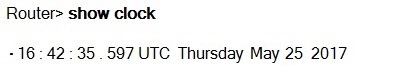
The following indicate whether the time is authoritative and synchronized:
(blank) Time is authoritative. Example:
Router> show clock detail
15:29:03.158 PST Thursday May 25 2017
Time source is NTP
In the above example, the time is authoritative and the time source is NTP. The clock is synchronized.
*Time is not authoritative. Ex: *15:29:03.158 PST Thursday May 25 2017
Time is authoritative, but NTP is not synchronized. Ex: .15:29:03.158 PST Thursday May 25 2017

